
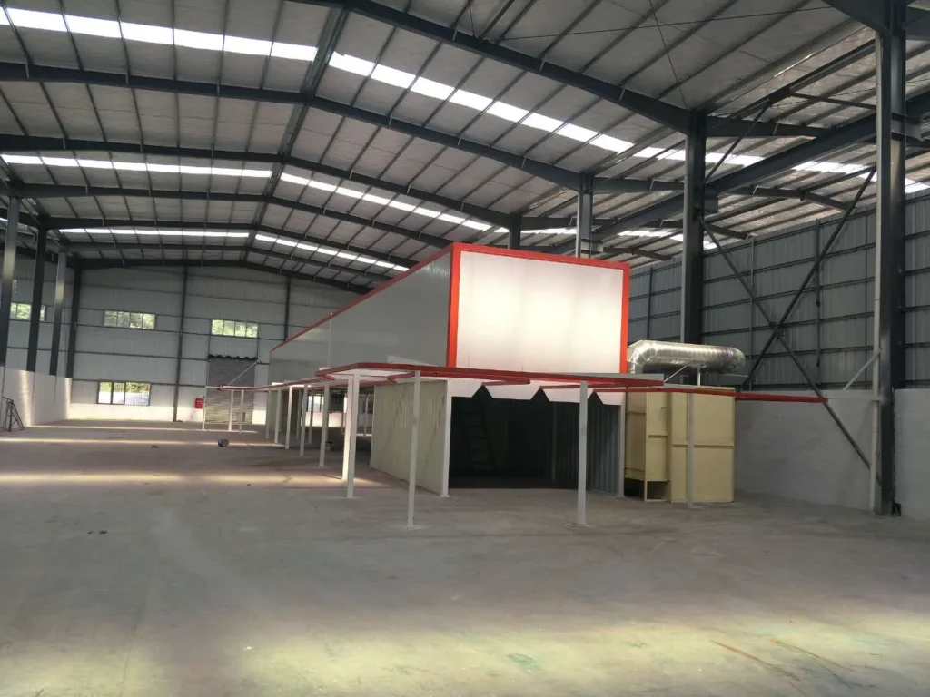
Does Metal Thickness Affect Powder Coating? Complete Guide to Process Impact, Parameter Adjustment & Multi-Thickness Production Solutions
Introduction
In electrostatic powder coating, metal thickness appears to be a minor specification detail—but it directly influences spray quality, process stability, production costs, and long-term coating performance. Many manufacturers focus on workpiece shape and output targets while overlooking how different substrate thicknesses actually behave during the entire coating cycle. This oversight often surfaces during production as uneven film thickness, color inconsistency, adhesion failure, or workpiece distortion.
From our experience running multiple electrostatic powder coating lines across cabinet, aluminum profile, and hardware manufacturing clients, we've seen that metal thickness mismatch is one of the most common—and most preventable—causes of quality variation. Many coating plants invest in premium equipment only to struggle with inconsistent results because they failed to account for substrate thickness differences during the design phase.
This article explores how metal thickness affects powder coating from both engineering and practical perspectives, covering thermal dynamics, electrostatic behavior, process parameter adjustment, and real-world solutions for handling mixed-thickness production on a single line.
How Metal Thickness Affects Powder Coating: The Five Core Impacts
Yes, metal thickness significantly affects powder coating results. The impact spans five interconnected areas:
1. Thermal Absorption and Heat Dissipation
Thin metal (0.5–2 mm):
- Heats up rapidly but also cools quickly
- Lower thermal mass means temperature spikes faster in the curing oven
- Risk of overcuring or thermal distortion if oven temperature is not reduced
- Requires lower bake settings and shorter dwell times to prevent surface degradation
Thick metal (3+ mm):
- Higher thermal mass ensures more uniform temperature distribution
- Heats more slowly but maintains stable temperature longer
- Better suited to standard or slightly elevated curing parameters
- May require longer dwell time to ensure complete internal cross-linking
2. Electrostatic Field Distribution and Powder Deposition
Thin substrates:
- Shorter grounding path = more stable electrostatic field
- Generally easier for powder to adhere uniformly
- However, thin workpieces can be displaced by spray gun air pressure
- Risk of positioning instability during spraying
Thick substrates:
- Longer grounding paths may increase contact resistance
- Larger mass resists air displacement, improving spray stability
- But increased complexity (recesses, holes, internal cavities) in thick workpieces creates more severe Faraday cage effects
- Powder has greater difficulty reaching internal edges and deep features
3. Coating Uniformity and Film Thickness Variation
Thin and thick metals respond differently to the same spray parameters:
- Thin metals: smaller surface area + faster heat absorption = less forgiving tolerance band for achieving uniform thickness
- Thick metals: larger surface area + thermal buffering = wider acceptable parameter window, but deeper recesses demand more careful spray coverage planning
4. Surface Finish Quality and Appearance
Thin metals are more prone to:
- Orange peel texture (due to rapid cooling and reduced flow-out time)
- Sag or runs (if film is too thick for rapid cooling)
- Brittleness in the cured layer
Thick metals typically exhibit:
- Better flow and leveling (more time for powder to melt and flow before cooling)
- More consistent gloss and color uniformity
- More robust final appearance
5. Production Efficiency and Line Design
- Thin metals demand: slower line speeds, lower oven temperatures, stricter climate control in the spray booth
- Thick metals allow: faster line speeds, standard oven profiles, more flexible spray booth conditions
This impacts overall throughput and energy consumption on the line.
Thin Metal vs. Thick Metal: Key Differences in Powder Coating Performance
Thermal Absorption & Heat Dissipation Differences
The thermal profile is where the starkest differences emerge:
| Parameter | Thin Metal (0.5–2 mm) | Thick Metal (3+ mm) |
|---|---|---|
| Heat-up time | 3–5 minutes to target | 8–12 minutes to target |
| Temperature stability | Rapid fluctuation risk | Gradual, stable climb |
| Cooling rate | Fast (risk of under-cure if line speed too high) | Moderate (more forgiving) |
| Optimal oven temp | 160–180°C | 180–220°C |
| Dwell time needed | 8–12 minutes | 12–20 minutes |
| Distortion risk | High if over-heated | Low |
Our observation: In mixed-thickness operations, we've found that one of the biggest mistakes is using a single oven temperature and time for both thin and thick substrates. The result is either under-cured thin parts or thermal stress on thin plates. The solution is either to run separate lines with different parameters, or to design a variable-speed oven that allows thick parts to spend more time at standard temperature while thin parts move through faster.
Electrostatic Charging & Grounding Effects
Thin metal advantages:
- Shorter grounding path = faster charge path establishment
- Less resistance = more stable, predictable electrostatic field
- Powder attracts uniformly across surface
Thin metal challenges:
- Light mass = easily displaced by spray gun air pressure
- Workpiece can shift or rotate during spraying, disrupting field alignment
- May require lower air pressure or spray gun adjustments
Thick metal advantages:
- Heavier mass = stable positioning during spray
- Can handle higher air pressures without movement
Thick metal challenges:
- Longer grounding path through fixture and workpiece
- Risk of contact resistance increases with corner or recessed areas
- Faraday cage effect more pronounced in internal cavities
- Powder "shadow" zones in deep recesses become harder to reach
Our recommendation: For mixed-thickness runs, always prioritize grounding continuity. Use conductive fixtures rated for the heaviest workpieces, maintain low contact resistance at all touch points, and verify grounding resistance regularly. We typically spec fixtures that can handle 150% of maximum workpiece weight for stability.
Coating Uniformity & Film Thickness Variation
Film thickness uniformity depends heavily on substrate thermal behavior:
Thin metals show:
- Higher variance in film thickness across surface (±15–20% typical)
- Faster solidification = less time for powder to flow and level
- Edge and corner buildup more noticeable
- Difficulty achieving thick films (>100 µm) without orange peel
Thick metals show:
- Lower variance (±8–12% typical)
- Better flow-out and leveling during heating
- More even edge distribution
- Easier to achieve thicker, more uniform coatings (100–150 µm)
Key insight: The "best thickness range" for powder coating typically assumes substrate thermal mass similar to industrial-grade metal (3+ mm). When you move to thin substrates, you must either reduce target film thickness or extend dwell time (or both) to achieve comparable uniformity.
Surface Finish Quality & Appearance
Visual quality differences are often the first sign of thickness-related problems:
| Finish Issue | Thin Metal | Thick Metal |
|---|---|---|
| Orange peel | Common (rapid cooling) | Rare (good flow time) |
| Color variation | More noticeable | Less noticeable |
| Gloss consistency | Variable | Consistent |
| Edge buildup | Pronounced | Moderate |
| Surface feel | May feel rough/uneven | Smooth, consistent |
Powder Coating Problems Specific to Thin Metals & How to Prevent Them
Thermal Warping and Distortion
What happens:
Thin metals heat to full curing temperature in 3–5 minutes. If oven temperature is set for thick substrates (190–220°C), thin parts can experience thermal shock, causing:
- Panel buckling or bowing
- Dimensional change (parts no longer fit assemblies)
- Stress marks or micro-cracking in coating
- Assembly fit problems downstream
Prevention strategies:
-
Lower oven temperature for thin substrates
- Target 160–180°C instead of 190–220°C
- Verify internal workpiece temperature (not just air temp) with thermal imaging
- Extend dwell time slightly to compensate
-
Increase line speed through curing section
- Faster movement limits total heat exposure
- Reduces peak temperature on thin parts
- May require longer total oven length to achieve same cure time
-
Reduce spray film thickness on thin parts
- Thinner films cure faster and generate less internal heat stress
- Target 50–80 µm DFT instead of 100+ µm
- Reduces both curing time and distortion risk
-
Use thermal simulation
- Model the part before production starts
- Calculate peak temperature reached at different oven positions
- Adjust line speed or oven temp zone accordingly
-
Implement part orientation control
- Position thin parts flat (not edge-on) to oven airflow
- Reduces asymmetric heating
- Improves temperature uniformity
Coating Adhesion Failure on Thin Substrates
Root causes:
- Insufficient pre-treatment (common on thin metal because operators rush)
- Poor electrostatic transfer due to workpiece movement
- Under-curing due to inadequate dwell time
- Residual moisture on surface before spray
Prevention:
-
Enforce rigorous pre-treatment
- Thin metals show adhesion problems faster, so don't compromise on cleaning
- Extend immersion time and ensure thorough rinsing
- Verify final surface is completely dry
-
Reduce electrostatic voltage slightly
- Lower voltage = less transfer force but also less risk of adhesion stress
- At 60–70 kV: good for thin metals; at 80+ kV: better for thick parts
- Balance transfer efficiency with adhesion robustness
-
Confirm adequate dwell time
- Minimum 8–10 minutes at proper temperature for thin metals
- Use time + temperature recorder to verify actual cure profile
- Don't sacrifice cure time to increase line speed
-
Test adhesion regularly
- Pull-off adhesion testing every shift
- X-cut test per ASTM D3359 for standard verification
- Track adhesion data to spot trends before field failures
Impact Damage from Spray Gun Force
Problem:
Thin workpieces can be dented, bent, or displaced by spray gun air pressure if:
- Spray pressure too high
- Distance too close
- Fixture holding is inadequate
Solutions:
-
Reduce spray air pressure
- Lower pressure = fewer deflection artifacts
- Acceptable range: 3–5 bar instead of 6–8 bar
- May require slower line speed or additional spray guns for coverage
-
Increase spray gun distance
- Move gun 200–250 mm from surface (vs. 150–180 mm for thick parts)
- Reduces direct force while maintaining decent deposition
- Requires higher voltage to compensate
-
Use friction spray technology
- Friction guns deposit powder with less air momentum
- Better for delicate thin substrates
- Higher control but slightly lower efficiency
-
Improve fixture design
- Support thin parts on multiple contact points
- Use distributed holding vs. single-point suspension
- Test fixture rigidity before production
Advantages & Challenges of Powder Coating Thick Metals
Superior Stability & Consistency
Key advantages:
| Aspect | Benefit |
|---|---|
| Thermal stability | Predictable curing; works with standard oven profiles |
| Positioning stability | Heavy mass resists spray air displacement |
| Grounding reliability | Larger contact area = lower resistance variation |
| Process repeatability | Parameter window wider; easier to maintain consistency |
| Film uniformity | Better powder flow = more uniform thickness distribution |
Real-world impact: On our cabinet production lines, workpieces with 2–3 mm gauge achieve first-pass adhesion rates >98% when pre-treatment and spray parameters are held constant. When we introduce thinner gauge parts to the same line, adhesion variance increases to 85–92% until we adjust parameters.

Faraday Cage Effect in Complex Geometries
What it is:
Interior surfaces, deep recesses, inner corners, and holes present electrostatic "shadow zones" where the electric field penetrates poorly. Powder particles have difficulty reaching these zones because the surrounding metal "shieldsElectric field lines.
Why it's more pronounced on thick metals:
- Thick metals are often used for structural cabinets, enclosures, or complex manifolds with many internal features
- Recesses are proportionally deeper relative to substrate dimensions
- More internal surfaces = more complex field geometry
How to address it:
-
Lower spray voltage
- Reduces field complexity; improves penetration into cavities
- Trade-off: slightly lower transfer efficiency
- Use 60–75 kV for complex thick parts; 75–90 kV for simple shapes
-
Use friction spray guns
- Deposit via friction, not just electrostatic attraction
- Better access to hard-to-reach areas
- Standard electric corona guns less effective for deep cavities
-
Adjust workpiece orientation
- Rotate or tilt to expose interior surfaces to spray gun
- May require custom fixtures
- Improves coverage on critical internal areas
-
Apply multiple spray passes
- First pass: 50–70 µm to key areas
- Second pass: final coat, filling remaining cavities
- Reduces powder waste vs. single long pass
-
Design for powder coating
- Communicate with product design: avoid sharp inside corners
- Specify draft angles and radii that improve powder access
- Reduces reliance on complex spray strategies
Curing Time & Penetration Requirements
Challenge:
Thick substrates have higher thermal mass. Powder on the surface cures quickly, but complete cross-linking throughout the coating—and any internal stress relief—requires longer dwell time.
Standard requirements:
| Substrate Thickness | Min. Dwell Time | Recommended Temp | Total Cure Time |
|---|---|---|---|
| 0.5–1 mm | 8–10 min | 160–180°C | 10–14 min |
| 2–3 mm | 12–15 min | 180–210°C | 15–20 min |
| 4+ mm | 15–20 min | 200–220°C | 20–25 min |
Why longer matters:
- Outer coating cures quickly (5–8 min at temp)
- Full cross-link reaction continues for 15–20 min
- Premature cooling = incomplete cure, reduced adhesion and hardness
- Over-curing (>25 min at high temp) risks yellowing and brittleness
Optimization:
- Use thermal imaging to measure actual part temperature at oven exit
- Don't rely on air temperature alone
- Adjust line speed or oven length to maintain dwell time within optimal window
Critical Process Parameters to Adjust for Different Metal Thicknesses
| Parameter | Thin Metal (0.5–2 mm) | Thick Metal (3+ mm) | Mixed-Thickness Strategy |
|---|---|---|---|
| Curing Temp | 160–180°C | 190–220°C | Use 175–190°C; extend dwell time |
| Oven Dwell | 8–12 min | 15–20 min | Variable speed or zone-based |
| Electrostatic Voltage | 60–75 kV | 75–90 kV | Start at 70 kV; adjust per part |
| Spray Distance | 200–250 mm | 150–180 mm | Set 200 mm; adjust angle for recesses |
| Powder Feed Rate | Reduced (60–80% standard) | Normal to high (90–110% standard) | Calibrate per thickness; test coverage |
| Line Speed | Slow (3–5 m/min) | Standard (6–10 m/min) | Variable speed oven or separate lines |
Curing Temperature & Dwell Time Settings
For thin metals:
- Lower oven temperature reduces thermal stress and distortion risk
- Compensate with longer dwell time to ensure full cure
- Typical profile: 170°C for 10–12 minutes
For thick metals:
- Standard to slightly elevated oven temperature is acceptable
- Sufficient thermal mass handles heat without distortion
- Typical profile: 200°C for 15–18 minutes
For mixed-thickness production:
-
Option 1: Use variable-speed conveyor through a standard oven
- Thin parts: faster throughput (shorter dwell)
- Thick parts: slower throughput (longer dwell)
- Single oven temperature (~185°C) works for both
-
Option 2: Zone-based oven with temperature gradients
- Zone 1: 160–170°C (pre-heat, low risk)
- Zone 2: 180–190°C (main cure)
- Zone 3: 170°C (cool-down)
- Allows both thin and thick parts in same zone
-
Option 3: Separate dedicated lines
- Highest quality but highest cost
- Best for high-volume, consistent-thickness production
Electrostatic Voltage & Spray Gun Distance
Voltage adjustment:
- Thin metals: 60–75 kV provides sufficient attraction without excessive transfer force or adhesion stress
- Thick metals: 75–90 kV needed for deeper cavities and more complex geometry
- Rule of thumb: Start at 70 kV; reduce for thin parts, increase for complex thick parts
Distance adjustment:
- Thin metals: 200–250 mm (reduces air pressure impact; maintains electrostatic field)
- Thick metals: 150–200 mm (improves efficiency for deep cavities; allows higher deposition rate)
- Check frequently: Distance variation ±20 mm creates noticeable film thickness variance
Why it matters:
- Distance affects both electrostatic field strength and spray air velocity
- Too close on thin parts = dimensional distortion + excessive force
- Too far on thick parts = poor cavity coverage + under-deposition
- Consistent distance = predictable, repeatable results
Powder Feed Rate & Line Speed Optimization
Feed rate by thickness:
| Thickness | Feed Rate (% of Standard) | Deposition Rate | Film Target |
|---|---|---|---|
| 0.5–1 mm | 60–75% | Reduced | 50–80 µm |
| 1–2 mm | 75–90% | Standard | 80–100 µm |
| 2–3 mm | 90–110% | Standard to high | 100–120 µm |
| 4+ mm | 110–130% | High | 120–150 µm |
Line speed optimization:
- Slow: 3–5 m/min (thin metals, complex geometry, high-quality requirement)
- Standard: 6–8 m/min (mid-range, most common industrial setting)
- Fast: 9–12 m/min (thick, simple geometry, high-volume production)
Key principle: Longer dwell time in spray zone = thicker, more uniform coating. If you need thicker film, either slow the line or add spray guns. Don't just increase feed rate, as that increases powder waste.
Can You Mix Different Metal Thicknesses on the Same Production Line?
Short answer: Yes, but with deliberate design and control.
Most modern manufacturing operates under pressure to handle multiple product variants on a single line. In cabinet shops, for example, you might need to spray frames (1.2 mm), door panels (0.8 mm), and reinforcement brackets (3 mm) all on the same equipment. The question is: how do you maintain quality across this range?
Design Considerations for Multi-Thickness Production
1. Fixture and Suspension System
- Design fixtures that support both light and heavy parts securely
- Use adjustable or modular fixtures that adapt to different part weights
- Verify grounding contact remains stable across all thickness ranges
- Test fixture rigidity at full operating load (thickest + heaviest parts)
2. Spray Gun Configuration - Multi-gun setups: allows selective engagement based on part geometry
- Position guns at angles and distances that work across thickness range
- For very different thicknesses (0.5 mm vs. 5 mm), consider multi-stage approach
3. Oven Zoning
- Divide oven into 2–3 zones with independent temperature control
- Zone 1: lower temp (160–170°C) for thin parts to pass through quickly
- Zone 2: standard temp (185–195°C) where most parts cure
- Zone 3: slightly elevated (205°C) for thick parts needing full penetration
- Parts spend different times in each zone based on conveyor speed
4. Conveyor Speed Control
- Variable frequency drive (VFD) on line motor allows speed adjustment per product variant
- Thin parts: faster (4–5 m/min)
- Mid-range: standard (7 m/min)
- Thick: slower (8–9 m/min)
- Reduces fixture congestion and ensures adequate spray/cure time
5. Pre-Production Setup
- Run test samples of each thickness variant before full production
- Verify curing profile, film uniformity, adhesion for each type
- Adjust spray parameters (voltage, distance, feed rate) per variant
- Document optimal settings in standard work or SOP
Equipment Configuration & Fixture Solutions
Recommended multi-thickness fixture design:
| Fixture Feature | Thin Metal Support | Thick Metal Support |
|---|---|---|
| Contact points | 4–6 (distributed) | 3–4 (concentrated) |
| Clamp force | Light (0.5–1 N) | Medium (2–3 N) |
| Grounding path | Direct, low resistance | Verified conductive track |
| Material | Aluminum or ductile iron | Steel |
| Thermal capability | 100°C max | 150°C+ |
Modular fixture example:
- Base frame: universal, accommodates all sizes
- Quick-change clamp blocks: sized for thin, mid-range, and thick parts
- Color-coded for easy identification
- Integrated grounding: ensures contact regardless of block size
- Change time: <5 minutes per variant
Grounding best practices:
- Verify contact resistance <1 Ω across all part types
- Clean contact surfaces regularly (oil, dust buildup increases resistance)
- Use conductive grease on contact points (improves stability)
- Test grounding before and after each setup change
Quality Control Strategies Across Thickness Ranges
1. Real-time monitoring:
- Install film thickness gauges at line exit to measure DFT per part
- Set upper/lower limits per product variant
- Flag out-of-spec parts before packing
- Track thickness data over time to identify drift
2. Regular sampling and testing:
- Pull samples every 30–50 parts per variant
- Test adhesion (ASTM D3359), hardness (pencil or Buchholz), impact resistance
- Verify appearance (gloss, color, orange peel) visually
- Keep records for traceability
3. Preventive parameter documentation:
- Create a parameter matrix showing optimal settings for each thickness
- Document voltage, distance, feed rate, line speed, oven temp/dwell
- Train operators on how to quickly switch configurations
- Laminate reference charts at spray station and oven control panel
4. Scheduled calibration:
- Verify electrostatic generator output monthly (should be stable ±3%)
- Check spray gun electrode cleanliness weekly
- Calibrate temperature sensors on oven quarterly
- Inspect conveyor speed accuracy monthly
5. Supplier quality communication:
- Inform powder supplier of mixed-thickness usage
- Request powder formulation optimized for 0.5–5 mm range
- Some powders flow better on thin substrates; others adhere better on thick
- Test powder samples before committing to large orders
Recommended Powder Coating Thickness Ranges by Application & Substrate Thickness
| Application | Substrate Gauge | Recommended DFT (µm) | Typical Temp/Dwell | Notes |
|---|---|---|---|---|
| Interior cabinet/enclosure | 1.2–2 mm | 80–100 | 180°C / 12 min | Standard industrial |
| Exterior cabinet/outdoor | 1.5–2.5 mm | 100–120 | 185°C / 14 min | Extra adhesion for harsh env. |
| Thin sheet metal parts | 0.5–1 mm | 50–80 | 165°C / 10 min | Lower temp to prevent distortion |
| Structural aluminum | 3–5 mm | 100–140 | 200°C / 16 min | Higher temp for full cure |
| High-corrosion environment | 2–4 mm | 120–150 | 200°C / 18 min | Max film for durability |
| Electrical/thermal critical | 1–2 mm | 50–75 | 175°C / 11 min | Thin coat to retain conductivity or heat dissipation |
Why recommendations vary:
- Thin metals need lower film thickness to avoid orange peel and thermal stress
- Thick metals can support and benefit from thicker coatings for durability
- Corrosive environments (salt spray, outdoor) benefit from thicker coatings but must have proper adhesion
- Thermal applications (heat sinks, electronic enclosures) may require thin coating to maintain heat transfer
Key principle: DFT should match both the substrate thermal capacity and the end-use requirement. Don't default to "thicker is better"—often the optimal thickness is a balance between protection and workability.
Key Takeaways: Ensuring Consistent Quality Across All Metal Thicknesses
From our experience managing multi-thickness production lines, here are the essential points:
-
Metal thickness directly affects thermal behavior. Thin metals heat and cool fast; thick metals heat slowly but maintain stable temperature. Design oven profiles and line speeds to match this difference.
-
Electrostatic field strength and spray gun distance must be adjusted per thickness. Thin parts need lower voltage and greater distance to avoid displacement and adhesion stress. Thick parts with complex geometry benefit from higher voltage and closer distance to reach cavities.
-
Pre-treatment becomes even more critical for thin substrates. Thin metals show adhesion problems faster than thick metals. Don't compromise on surface cleaning, drying, or pretreatment time.
-
Single-parameter operation fails in mixed-thickness environments. You need either variable-speed conveyors with zone-based oven control, or separate dedicated lines for very different thickness ranges.
-
Film thickness should be calibrated to substrate thickness, not applied uniformly across all variants. Thin parts: 50–80 µm. Thick parts: 100–150 µm. Uniform thickness causes either under-spec or over-spec quality.
-
Fixture design matters more than many realize. Poor grounding contact, inadequate support, or excessive clamping force on thin parts causes quality variance that no spray parameter adjustment can overcome.
-
Monitor and document everything. Use DFT gauges, adhesion tests, and hardness checks to track performance per thickness variant. This data is your early warning system for drift.
-
Invest in operator training specific to thickness variants. Your equipment is only as good as the people running it. Make sure line operators understand why and how parameters change between thin and thick production.
-
Test new product variants on pilot scale before full production. Run 50–100 parts of a new thickness, verify all quality parameters, then scale up. This avoids costly scrap from parameter miscalibration.
-
The 80/20 rule applies here too. Most quality issues in mixed-thickness operations trace back to inadequate pre-treatment, incorrect oven dwell time, or poor fixture grounding—not exotic spray gun settings. Fix the fundamentals first.
Contact Us for Custom Coating Line Solutions
At Ketu, we've designed and implemented electrostatic powder coating systems for manufacturers dealing with single-thickness and multi-thickness production challenges across cabinet, furniture, aluminum profile, and hardware sectors.
If your operation handles varying metal gauges and you're struggling with consistency, adhesion, or appearance quality, we'd welcome the opportunity to discuss your specific requirements. We can help you:
- Assess current line limitations with mixed-thickness production
- Design customized fixtures and spray configurations suited to your product range
- Optimize oven profiles for reliable curing across thickness variants
- Implement real-time quality monitoring to catch drift before scrap occurs
- Train your team on parameter management for multi-thickness operations
Reach out to discuss your project:
- WhatsApp: +8618925987762
- Email: ketucoatingline@gmail.com
We look forward to partnering with you to ensure consistent, high-quality coating results regardless of metal thickness.
 English
  German
  Vietnamese
  French