

KetuTechnology After-Sales Support: Systematic Diagnosis and Solutions for Common Electrostatic Spraying Process Issues
When you're running an electrostatic powder coating line, surface defects can appear suddenly and frustrate your entire production schedule. Pinholes, poor adhesion, uneven film thickness, color deviations—these issues look simple on the surface but often reveal deeper system problems. From my experience working with cabinet manufacturers, furniture producers, and aluminum profile makers across multiple countries, I've learned that 70% of visible coating defects actually originate in stages most operators overlook or misdiagnose.
This is where structured troubleshooting becomes critical. Rather than randomly adjusting spray gun voltage or blaming powder quality, I'll walk you through the systematic diagnostic approach we've developed at Ketu—one that helps our after-sales team and client technicians identify root causes quickly and fix them permanently.
Why Pre-Treatment Failures Account for 70% of Electrostatic Spraying Defects
In our after-sales visits across cabinet factories in Algeria, furniture plants in Turkey, and aluminum mills in India, I've observed a consistent pattern: when operators encounter coating problems, their first instinct is usually to adjust the spray gun. But when we dig deeper, nearly 7 out of 10 times the real issue started in the pre-treatment stage.
The Root Cause Reality
Pre-treatment is not just a "preparatory step." It's the foundation on which everything else depends. If this stage fails, no adjustment to spray parameters or curing temperature will reliably restore quality. Here's what typically goes wrong:
| Pre-Treatment Issue | Resulting Defect | Why It's Hard to Spot |
|---|---|---|
| Oil residue on surface | Pinholes, crawling, poor adhesion | Defects appear random; only visible after coating hardens |
| Incomplete rust removal | Spot corrosion, layer separation | Develops over weeks or months; looks fine initially |
| Salt contamination | Blister formation, delamination | Salt is invisible; only shows after exposure |
| Insufficient drying | Pinholes, shrinkage, gas bubbles | Moisture evaporates during curing, leaving voids |
| Wrong phosphate thickness | Weak adhesion layer, salt fog failure | Affects long-term performance, not immediate appearance |
What We've Learned
Based on hundreds of line commissionings, when I systematically strengthen pre-treatment control—verifying degreasing concentration, temperature, spray pressure, immersion time, and especially drying completeness—surface defect rates typically drop by 40–60%. This alone often resolves adhesion issues that clients initially attributed to powder quality or electrostatic voltage problems.
Pre-Treatment Control Checklist
Before you touch spray parameters, verify:
- Degreasing stage: Solution pH within range, temperature stable (typically 50–70°C), spray pressure 2–4 bar, contact time 1–3 minutes minimum
- Rinsing sequence: Each rinse should be visibly clean; if water beads up rather than spreading, incomplete degreasing
- Phosphate/conversion coating: Layer thickness 10–25 g/m² (target your material type); dwell time adequate for reaction
- Final rinse: Use demineralized or DI water[^1] if possible; tap water minerals can leave residue
- Drying: Measure workpiece surface temperature—it must reach 50°C+ to drive off all moisture. Cold spots = moisture traps
Systematic Troubleshooting: How to Diagnose Surface Defects Like Pinholes, Shrinkage, and Poor Adhesion
I've learned to diagnose coating defects using a structured sequence rather than guessing. This approach works whether you're troubleshooting offline or performing live line diagnostics.
Surface Defect Identification and Root Cause Analysis
Pinholes and Micro-Voids
Visual signature: Tiny crater-like holes scattered across the surface, often 0.5–2 mm diameter. Interior appears darker than surrounding coating.
Primary causes (in order of probability):
- Moisture on workpiece surface (50% of cases I see)
- Contaminated compressed air[^2] (water or oil droplets)
- Outgassing from workpiece substrate (especially hollow parts or porous materials)
- Powder itself too fine or hygroscopic (absorbed atmospheric moisture in storage)
Diagnostic steps:
- First, touch the workpiece immediately after drying—it should feel bone dry to touch, not just warm
- If defects appear only after a few hours of production, suspect moisture
- Check compressed air outlet for water beads or oily film
- If only hollow workpieces show pinholes, suspect internal outgassing—verify adequate drying time
Shrinkage and Cratering
Visual signature: Irregular depressions where coating appears to have pulled away from substrate; edges are slightly raised. Often concentrated in corners or complex geometry areas.
Primary causes:
- Surface contamination (dust, silicone, release agent residue)
- Powder inadequate flow-out during melting phase
- Substrate temperature too low, preventing powder fusion
- High electrostatic field causing powder to "bounce" before proper settling
Diagnostic steps:
- Wipe test: Clean a sample area with isopropyl alcohol; if defects persist, it's not surface contamination
- Check curing temperature profile—is the workpiece reaching target temperature across all surfaces?
- Inspect spray room air; visible dust clouds indicate air quality issues
- Reduce spray gun voltage slightly; sometimes over-charging causes powder instability
Poor Adhesion and Delamination
Visual signature: Coating separates from substrate under mechanical stress (tape test, bend test, or spontaneous flaking at edges). Failure typically happens along a clear interface.
Primary causes:
- Pre-treatment inadequate (most common in our experience)
- Fixturing or electrode contact points corroded or contaminated
- Workpiece grounding intermittent during spray cycle
- Curing incomplete or parameters incorrect
- Substrate contamination after pre-treatment but before coating
Diagnostic steps:
- Perform pull-off adhesion testing (ASTM D4541[^3] standard): coating should not separate at <5 MPa
- Check grounding path: measure electrical resistance from workpiece to ground—should be <1 ohm
- Inspect electrodes and contact points for oxidation or powder buildup; clean if necessary
- Review pre-treatment parameters; if recently changed, revert and compare results
Parameter Adjustment Sequence and Verification Method
Once you've identified the likely defect category, adjust parameters in this specific order. This sequence minimizes trial-and-error and helps isolate which parameter actually caused the improvement.
Step 1: Verify and Correct Grounding
Before changing anything else, confirm workpiece grounding is reliable.
- Clean all contact points (electrode, hanging fixture, product-to-fixture contact)
- Measure grounding resistance; if >1 ohm, improve contact or clean oxidation
- Verify grounding cable is intact and not kinked
Why first? Grounding failures disrupt the entire electrostatic charge transfer. No other adjustment matters if charge can't reach the workpiece.
Step 2: Stabilize Line Speed
Check conveyor speed consistency; even ±10% variation causes membrane thickness fluctuation.
- Run a full cycle with marked workpieces; measure spacing—should be uniform
- Verify timing between workpiece position and spray gun activation—tolerance within 100 ms
- If speed fluctuates, check drive motor, belts, and sensor calibration
Why second? Line speed directly governs spray dwell time and powder transfer time. Inconsistent speed creates coating thickness scatter before spray parameters even factor in.
Step 3: Adjust Spray Gun Parameters (in this order)
3a. Spray Gun Voltage & Current
- Start at manufacturer recommendation (typically 60–90 kV for most systems)
- If film looks thin or uneven, increase voltage incrementally by 5 kV
- Monitor current output; should remain within 10–20 μA range
- If current spikes >20 μA, reduce voltage slightly—indicates overstressing
3b. Spray Gun Distance
- Optimal range usually 150–250 mm for corona-type guns
- If distance too close (<150 mm): powder stacks, edges thicken, edge-burn risk
- If distance too far (>300 mm): powder scatter increases, efficiency drops, upper surface coverage weakens
- Adjust incrementally; every 25 mm shift is measurable
3c. Spray Gun Angle
- For simple flat surfaces: perpendicular (90°) is standard
- For complex geometry: adjust gun angle to penetrate recesses without creating edge buildup
- For internal cavities (Faraday cage problem): typically 30–45° helps powder enter confined areas
3d. Powder Supply Rate
- Increase if film looks thin (target film thickness not achieved)
- Decrease if powder bounces or edges accumulate
- Typical adjustment: ±10% at a time, then wait for 3–5 cycles before judging
Verification protocol: After each adjustment, spray 3–5 test samples and measure film thickness at 5 points (center, 4 edges) using a coating thickness gauge. Record data in a simple table—this creates an audit trail and reveals parameter-to-thickness relationship.
How to Overcome the Faraday Cage Effect in Complex Workpiece Coating
Cabinet bodies, deep-draw metal parts, and internal cavities create what's called the Faraday cage[^4] effect: electrostatic field lines concentrate on the outside, leaving interior surfaces undercharged and poorly coated.
Causes and Impact Assessment
The Faraday cage effect occurs because electrostatic field lines naturally crowd around external edges and corners. Inside recessed areas, the field strength drops sharply, so powder particles lose charge and don't adhere well.
Impact by Geometry Type:
| Part Geometry | Faraday Effect Severity | Typical Under-Coated Area |
|---|---|---|
| Deep boxes, enclosures | High | Interior surfaces, recessed edges |
| Channels and slots | Medium-High | Bottom of slot, internal corners |
| Holes and perforations | Medium | Hole interior edges |
| Shallow recesses | Low-Medium | Recessed floor |
| Flat surfaces | None | N/A |
In our cabinet and aluminum profile projects, the Faraday cage effect typically causes 15–40% film thickness reduction in affected internal areas—enough to compromise adhesion and corrosion resistance.
Low-Voltage Multi-Pass Strategy vs. High-Voltage Single-Pass Trade-Offs
Rather than cranking voltage to compensate (which causes edge overspray and waste), we employ multi-pass or geometry-adapted techniques.
Strategy 1: Lower Voltage + Multi-Pass Spray
Method:
- Reduce spray gun voltage to 50–60 kV (lower than standard)
- Spray the workpiece once from primary angle
- Rotate workpiece or adjust part position
- Spray again from secondary angle (45° offset or perpendicular)
Advantages:
- Powder settles gently; less bounce-back and waste
- Complex areas receive powder from multiple approach vectors
- More uniform final thickness, including internal surfaces
- Typically 15–25% improvement in internal area coating
Disadvantages:
- Requires 2x spray time per workpiece
- Reduces line throughput by ~40%
Strategy 2: Single-Pass High Voltage + Geometry Workaround
Method:
- Maintain standard voltage (70–85 kV)
- Reposition spray gun or workpiece jig to approach cavity from optimal angle
- Example: for a box with deep internal cavity, position gun 30° off-perpendicular to direct powder toward cavity opening
Advantages:
- Single pass; no throughput penalty
- Uses existing line infrastructure
Disadvantages:
- External edges risk overcoverage and waste
- May not fully penetrate very deep cavities
Our Recommended Hybrid Approach (based on hundreds of line tests):
For workpieces with moderate Faraday cage risk:
- Spray at 65–70 kV (slightly lower than maximum)
- Adjust gun angle or part rotation to favor cavity entry
- Increase spray dwell time by 20–30% (slower line speed for this workpiece zone only)
- If still inadequate, introduce a second spray position at 45° angle, operating at lower voltage (50 kV) and lower powder flow
This hybrid reduces defects in 8–9 out of 10 complex-geometry projects we commission.
Compressed Air Quality: The Hidden Factor Behind Coating Defects
I cannot overstate how often compressed air quality is overlooked. In my service calls, when operators complain of unexplained pinholes or inconsistent powder flow, the root cause traces back to air system contamination in roughly 4 out of 10 cases.
Common Air Contamination Types and Their Defect Signatures
Water Contamination (Most Common)
Source: Atmospheric moisture condensing in compressor tanks and lines, especially in humid climates or when compressor runs continuously.
Defect signature:
- Pinholes and tiny voids scattered across coating surface
- Powder clumping in supply hopper (moisture causes agglomeration)
- Inconsistent powder flow—some cycles light powder, next cycle heavy
Detection method:
- Hold a clean white cloth at spray gun air outlet for 10 seconds
- Visible water beads or mist = water contamination confirmed
- If moisture settles as droplets, water content is >5 mg/m³ (bad)
Oil Contamination (Second Most Common)
Source: Compressor lubricant carryover, especially in older or poorly maintained units. Also airborne from shop machinery.
Defect signature:
- Coating surface appears dull or "crawled" (doesn't spread evenly)
- Adhesion poor; coating separates in patches
- If severe, visible greasy sheen on powder before spray
Detection method:
- Run compressed air into a clean glass container for 1 minute
- If oily film coats container interior, oil contamination confirmed
Particulate Contamination (Dust and Scale)
Source: Compressor internal corrosion, pipe scale from rusty lines, or external dust entering through intake.
Defect signature:
- Visible specks or grit on powder coating
- Powder doesn't flow smoothly; jamming in supply lines
- Supply tube blockages every few shifts
Detection method:
- Inspect compressed air outlet with a white tissue; trapped particles visible immediately
Air Treatment System Setup and Maintenance Standards
For reliable electrostatic powder coating, I recommend this three-stage air treatment[^5] architecture:
Stage 1: Moisture Removal
Equipment: Refrigerated dryer or desiccant dryer
Target specification: Dew point -20°C or lower
- Refrigerated dryer: Simpler, lower initial cost; adequate for most production environments
- Desiccant dryer: Better dew point; preferred for high-humidity climates or continuous 24/7 operation
Maintenance: Drain moisture trap daily; check/replace dryer cartridge per manufacturer interval (typically every 6–12 months)
Stage 2: Coarse Filtration
Equipment: Inline particulate filter, 10–25 micron rating
Pressure drop budget: <0.2 bar
Maintenance: Check filter element weekly; replace when pressure differential exceeds manufacturer spec (typically 0.5–1.0 bar). Clogged filters reduce air supply velocity, affecting powder flow consistency.
Stage 3: Fine Filtration + Oil Removal
Equipment: Combination filter, 3–5 micron, with activated carbon or coalescing stage
Pressure drop budget: <0.1 bar
Maintenance: Replace filter cartridge every 3–6 months, depending on shop air quality; inspect monthly.
Maintenance Schedule (Ketu Standard):
| Task | Frequency | Who |
|---|---|---|
| Drain moisture trap | Daily (end of shift) | Line operator |
| Visually inspect dryer function | Weekly | Maintenance technician |
| Check filter pressure differential | Weekly | Maintenance technician |
| Replace coarse filter element | Every 6 months or when ΔP >0.5 bar | Maintenance technician |
| Replace fine filter element | Every 3–6 months | Maintenance technician |
| Full air system integrity check | Every 12 months | Ketu service or certified technician |
Real Impact: In one aluminum profile factory in India where we installed a proper three-stage air treatment system, pinholes dropped from ~8% defect rate to <1.5% within two weeks—no other line changes.
Parameter Matching Protocol: Solving Uneven Film Thickness and Color Deviation
Uneven film thickness and color inconsistency often look like spray gun or powder problems, but in reality they stem from parameter misalignment across the entire line. Here's the diagnostic protocol I use in after-sales situations.
Diagnosis Sequence (Grounding → Line Speed → Gun Timing → Loading Density)
Phase 1: Grounding Integrity Check
Uneven coating thickness often indicates inconsistent charge transfer. Start here:
- Measure resistance from workpiece jig to ground at multiple points: minimum 3 contact areas (e.g., two hanging points + one fixture contact)
- All measurements should be <1 ohm; if any >2 ohms, clean contact points or improve electrode design
- Resistance drift during production (e.g., starts at 0.5 ohm, climbs to 2 ohm after 100 cycles) signals oxide buildup—requires maintenance
Phase 2: Line Speed Consistency
Conveyor speed variation directly causes thickness variation:
- Mark workpieces at entry and measure spacing at exit; variance should be <3%
- If spacing irregular, check for speed oscillations using a tachometer at the drive pulley
- Typical root causes: worn drive belt slippage, motor frequency drift, or worn sprocket teeth
Phase 3: Spray Gun Timing Synchronization
Gun activation must precisely align with workpiece position:
- Verify sensor (proximity or photoelectric) triggers gun spray exactly when workpiece enters the spray zone
- Test with marked samples; mark should be visible on every piece at the same position
- Timing drift >50 ms causes some pieces to receive under-spray, others over-spray
Phase 4: Hanging Density and Geometry Consistency
Workpiece placement affects local spray coverage:
- Ensure pieces hang at identical vertical height; height variance >25 mm can shift effective spray distance
- Confirm pieces don't touch or nest during spray; contact prevents powder access to hidden areas
- Verify jig orientation is consistent; rotated jigs change angle relative to spray direction
Real-Time Monitoring and Quick-Fix Adjustments
Rather than waiting for offline testing, implement live thickness monitoring:
On-Line Measurement Approach:
- Measure every 10th workpiece with a portable coating thickness gauge immediately after spray room exit (before curing)
- Record in simple spreadsheet: Piece #, Center thickness, Corner thickness, Time
- Alert threshold: If any single piece >15 μm or <50 μm from target, stop line and diagnose before next batch
Quick-Fix Decision Tree:
| Observed Pattern | Likely Cause | Quick Fix |
|---|---|---|
| All pieces thin uniformly | Powder supply too low or voltage too low | Increase powder flow by 5–10%; verify supply hopper isn't low |
| All pieces thick uniformly | Powder supply too high | Reduce powder flow; check line speed hasn't slowed |
| Thick at entry, thin at exit | Line speed drifting (accelerating) or gun voltage drifting | Check tachometer; verify PLC spray timing hasn't shifted |
| Thin at corners/edges, thick at center | Spray distance too far or gun angle not optimal | Reduce spray distance 25 mm; adjust gun angle to center corners |
| Sporadic thin spots | Workpiece geometry variance or jig contact issues | Inspect jig fitment; ensure workpieces aren't touching |
Curing Status Diagnosis: Distinguishing Under-Curing from Over-Curing
Curing problems are often mistaken for pre-coating defects. I've seen customers repeatedly adjust spray parameters when the real issue was in the oven. Systematic curing diagnosis saves weeks of frustration.
Visual and Tactile Indicators for Each Condition
Under-Curing Signs:
Visual:
- Coating appears dull, lacks gloss
- Color slightly muted compared to reference sample
- Surface feels slightly tacky to touch (even after cooling)
- Fails MEK[^6] (methyl ethyl ketone) rub test—coating visibly softens after 10 rubs
Tactile:
- Thumbnail easily leaves indentation mark
- Coating bends without cracking when flexed (indicates incomplete cross-linking)
Over-Curing Signs:
Visual:
- Coating appears yellowed or darkened compared to fresh reference
- Gloss diminished (paradoxically, too much cure can reduce gloss)
- Color shift visible (especially noticeable with lighter colors)
- Surface feels dry and slightly brittle
Tactile:
- Brittle fracture when bent sharply (indicates embrittlement from excessive cross-linking)
- Surface scratches more easily than properly cured piece
Curing Curve Testing and Temperature Adjustment Guidelines
To distinguish oven-stage problems from elsewhere, implement a curing profile test:
Curing Curve Test Protocol:
- Spray 5 identical test samples with powder you know is good quality
- Extract samples from oven at 2-minute intervals (0, 2, 4, 6, 8, 10 minutes into oven)
- Cool samples to room temperature (typically 1–2 hours)
- Perform hardness and adhesion testing:
- Pencil hardness (ASTM D3363[^7]): Should reach target (typically H or 2H) by mid-cycle
- MEK rub test: Should pass (no softening) by final-cycle sample
- Bend test: Should withstand 180° bend without cracking
Interpreting Curing Curve Results:
| Sample Position | Observation | Interpretation |
|---|---|---|
| 0–2 min sample | Completely soft, fails adhesion | Oven temperature too low at entry OR workpiece temperature doesn't match setpoint |
| 4–6 min sample | Still soft, slight hardening trend | Oven temperature profile is sluggish; either temperature setpoint too low or hot air circulation weak |
| 8–10 min sample | Proper hardness, good adhesion | Curing complete; oven parameters correct |
| 10+ min sample (if tested) | Yellowing or brittleness vs. 8 min | Over-curing; reduce residence time or lower final-stage temperature |
Temperature Adjustment Guidance:
- Insufficient hardening by mid-oven: Increase oven setpoint by 5–10°C; retest in 2 hours
- Excessive yellowing: Reduce final oven zone temperature by 5°C or reduce total dwell time by 2–3 minutes
- Color drift between day shift and night shift: Likely thermal inertia; ensure oven reaches steady-state (30+ min preheat) before production
Critical Measurement: Use an infrared thermometer to verify actual workpiece surface temperature, not just air temperature inside the oven. Thick workpieces (>3 mm) may lag 10–20°C behind oven setpoint—this is a common hidden cause of under-curing.

Pre-Production Checklist: Preventing Defects Before the First Spray Cycle
The easiest defects to fix are the ones you prevent. Before running a new product or restarting after a color change, execute this checklist systematically.
Powder Supply and Recovery System Preparation
Powder Hopper & Supply System:
- [ ] Inspect hopper interior for caking or settled powder from previous run; vacuum clean if needed
- [ ] Verify hopper temperature stable (typically 15–25°C); cold powder is hygroscopic and won't flow reliably
- [ ] Check flow slide gate moves freely; any resistance indicates powder bridging
- [ ] Confirm powder pump displacement matches production rate (review PM manual if unsure)
- [ ] Inspect powder feed tube interior for clogs using a clean rod; blockage anywhere causes supply surges
Compressed Air System (Before Powder Activation):
- [ ] Drain all air lines at lowest points; visible water confirms moisture in system
- [ ] Check dryer function: verify outlet air is dry (tissue method—no beading)
- [ ] Inspect filter elements; if pressure differential gauge shows >70% of max, replace before production
- [ ] Verify air flow at spray gun outlet using tissue; air should flow steadily (not pulsing)
- [ ] Test pressure regulator: should maintain 4–6 bar consistently; fluctuation >0.5 bar signals regulator wear
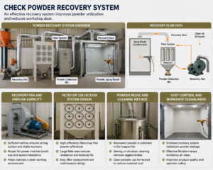
Recovery & Recycling System:
- [ ] Empty collection hopper and second-stage collection bin
- [ ] Confirm cyclone separator baffles clear (no powder stuck in air path)
- [ ] Inspect filter cartridges in secondary recovery: if last run was heavy, consider preemptive replacement
- [ ] Verify balance of recovered powder: should be free-flowing and uniform color (no settling or stratification)
Quality Check on Recovered Powder:
Before blending recovered powder back into fresh supply:
- Visual inspection: no visible contamination (different color flecks, dust, moisture clumps)
- Flow test: recovered powder should pour freely; any clumping means moisture pickup—discard
- Mix ratio: maximum 30% recovered powder + 70% fresh is our typical standard; more recovered material increases defect risk
Color-Change Protocol and System Purging Standards
Pre-Color-Change Inspection:
- [ ] Note the previous color and new color; determine if they are compatible (e.g., don't run white after dark color without thorough purge)
- [ ] Inspect spray gun electrode and tip for caked-on powder from previous color; use nylon brush (not metal) to gently clean
Purging Sequence:
-
Air purge only (3–5 minutes):
- Activate compressed air supply to spray gun
- No powder; just air flowing through gun
- Purpose: blow out loose powder remnants
-
Sacrifice material spray (1–2 minutes):
- Activate spray gun with fresh new-color powder loaded
- Spray onto scrap substrate or recovery chamber (not into trash—powder is recoverable)
- Purpose: flush residual old color from lines and gun
-
Verification spray (1 piece):
- Spray one actual test workpiece
- Inspect for color contamination (old color mixed with new)
- If contamination visible, repeat step 2
-
Restart production:
- If verification piece passes, begin production
- Hold first 5 pieces for color verification before shipping
System Purging Standards:
| Parameter | Standard | Acceptable Range |
|---|---|---|
| Air purge duration | 5 min | 3–7 min depending on powder type |
| Sacrifice material quantity | 0.5–1.0 kg | Up to 1.5 kg if previous color very different |
| Verification pieces | 1–3 | Up to 5 if switching to white or light colors |
| Time from first sacrifice spray to first production piece | <30 min | <60 min in emergency; beyond 60 min, risk powder settling and re-contamination |
How to Choose the Right Diagnostic Sequence for Your Line
Not every defect requires full diagnostic protocol. Use this decision tree to prioritize:
Quick Filter Questions:
-
Is the defect appearing on ALL pieces consistently?
- Yes → Focus on pre-treatment, oven parameters, or air quality
- No → Focus on spray gun parameters or workpiece geometry variance
-
Does the defect appear immediately after a known change (new powder batch, line speed adjustment, operator, or color change)?
- Yes → Revert that change first; if defect disappears, change was root cause
- No → Systemic issue; likely pre-treatment or oven
-
Have you tested samples from different zones on the line (entry, middle, exit)?
- No → Do this first; determines if problem is localized or system-wide
- Yes, and defects worse at exit → Suspect oven under-curing
- Yes, and defects worse at entry → Suspect pre-treatment or air quality
Conclusion: Building a Stable, Predictable Coating Process
After supporting electrostatic powder coating lines for cabinet makers in Algeria, furniture manufacturers in Turkey, and aluminum mills in India, I can confirm that the most successful plants aren't necessarily those with the newest equipment—they're the ones that use diagnostic discipline.
Most coating defects stem from one of six core system failures:
- Pre-treatment inadequacy (70% of adhesion issues)
- Air contamination (40–50% of surface defects like pinholes)
- Grounding instability (accounts for unpredictable thickness variance)
- Parameter misalignment (spray distance, voltage, and line speed must coordinate)
- Geometry-specific challenges (Faraday cage effects in complex parts)
- Curing parameter drift (over or under-curing distorts final appearance and performance)
The systematic approach I've outlined here—starting with pre-treatment verification, moving through compressed air quality checks, confirming grounding, then adjusting spray parameters in sequence—eliminates guesswork and cuts troubleshooting time by 60–70% compared to random parameter tweaking.
If your team is experiencing recurring surface defects or inconsistent quality, I recommend implementing the pre-production checklist and the real-time thickness monitoring protocol outlined above. Both are low-cost interventions that typically pay for themselves within weeks by reducing scrap and rework.
What's your most pressing coating challenge right now? Whether it's pinholes on aluminum profiles, adhesion issues on cabinet bodies, or color inconsistency on furniture, the diagnostic frameworks in this article provide a clear path forward.
If you'd like to discuss your specific situation or explore how our after-sales support and technical consultation can help your operation, I'm available to connect directly. You can reach our team at WhatsApp: +8618064668879 or email ketucoatingline@gmail.com to arrange a technical consultation or on-site diagnostics session.
Stable, predictable coating quality is achievable—and it starts with systematic diagnosis, not random adjustment.
[^1]: Process and benefits of removing mineral ions from water for precision applications in coating pre-treatment systems.
[^2]: Gas at pressure greater than atmospheric pressure, used in coating processes for air supply, atomization, and powder feed systems.
[^3]: Standard test method for measuring adhesion strength of coatings using a pull-off tester to determine interface failure loads.
[^4]: Shielding effect where conductive surfaces block electric field penetration into enclosed cavities, reducing powder deposition on interior surfaces.
[^5]: International standards framework for air treatment quality specifications including moisture removal, filtration, and contamination control requirements.
[^6]: Volatile organic solvent used in rub tests to assess curing completeness and cross-linking density of powder coating finishes.
[^7]: Standard test method for determining pencil hardness of coatings by resistance to scratching with calibrated pencil grades.
 English
 German
 Vietnamese
 French